 All materials on this site © PAR Electronics, Inc.
PAR Electronics, Inc.
P.O Box 645
Glenville, NC 28736
Voice: 828-743-1338
Fax: 866-304-8479
Email us if you have questions or comments about this site.
Site by
Pinnacle Web Design
1296 MHz EME (Earth-Moon-Earth)
Listen to the EME signals:
HB9Q heard at W4OP
W4OP heard at K1RQG
W4OP echo testing
G4CCH working S59DCD as heard at W4OP Jan 16, 2016
Download another nice intro to EME by Ben, W4SC (PDF, 1.7MB)
2015 DUBUS 23cM EME Log from W4OP and W4SC 2nd operator
EME, or moonbounce as it is commonly known, is the most exotic means of communicating for radio amateurs, and is not to be compared to active satellite communications. The path loss from earth to moon back to earth at 1296MHz is a whopping 271dB. That means, of the signal that goes out, the fraction that comes back to earth is 1/1,000,000,000,000,000,000,000,000,000.
")
Here is a nice introduction to EME from Paul, N1BUG. Published with his permission:
Although not really an efficient reflector (reflecting only about 7% of the signal that hits it), the moon is capable of reflecting enough of a VHF or UHF signal back to Earth to allow communication between well-equipped stations. Working range on EME is primarily limited by moon visibility. If two stations can simultaneously see the moon, they will be able to make contact (assuming adequate power, antennas, etc. for EME work). However, due to variability in conditions, several attempts may be required to achieve success. The round trip path is nearly half a million miles. Path loss varies with frequency, ranging from about 243 dB at 50 MHz to 289 dB at 10,368 MHz.
EME signals fade in and out for a number of reasons. Sometimes you hear nothing for long periods of time. Other times you will be amazed what you can hear.
The polarization of EME signals is constantly changing. Except for a few stations who can rotate or electrically switch the polarization of their antennas, this causes very deep QSB that can last from several minutes to several hours or even days. There is also such a thing as true one way propagation on EME, largely due to polarization shifting. Sometimes, both stations hear each other; sometimes, A can hear B but not vice versa; sometimes B can hear A; and sometimes neither can hear the other. There are two basic polarization effects. Spatial polarization: two stations using linear polarization arrays with azimuth/elevation mounts will usually not have their antennas aligned in polarization as seen by the moon. Faraday rotation: actual rotation of the wave front as it passes through the ionosphere. Spatial polarization is the dominant factor at 1296 MHz and above where ionospheric affects are minimal.
The moon follows many cycles. The distance between the Earth and the moon is not constant. It varies, and generally there will be a perigee (moon closest to Earth) and an apogee (moon farthest from Earth) each month. Path loss to the moon and back is roughly 2 dB less at perigee than at apogee. This can make a very noticeable difference for small stations. Also, the sky behind the moon can be very noisy at certain times. All planets, stars, etc., emit noise across the radio spectrum, and most EME systems are sensitive enough to hear this noise. Sky noise is generally at its worst when the moon is crossing the galactic plane (moon appears in the Milky Way), which occurs twice each month. Practically all software intended for EME use includes this data. You can download Z-Track from this site, but there are several other equally good programs available. Sky noise is more of a problem at the lower frequencies.
Signals also tend to exhibit a rapid, almost fluttery fading known as libration fading. This is caused by the irregular surface of the moon, which “rocks back and forth” slightly as viewed from Earth. Libration can cause signals to go both above and below the average level. Libration peaks, which can last up to a couple of seconds at 2 meters, can actually help the small station make contacts they would not be able to otherwise. This phenomenon is of little use at higher frequencies, as the rete of libration fading is directly proportional to frequency (the fading is faster on higher frequencies). Thus, a libration peak that lasts 3 seconds on 144 MHz will only be one second on 432, and 1/3 of a second on 1296.
Because the moon moves in relation to Earth, there is a slight doppler shift on EME signals. The amount of doppler shift is proportional to frequency. It is about 350 Hz maximum on 144 MHz, more on higher frequencies. At moonrise, the doppler shift is upward in frequency, reaching zero as the moon passes overhead, and then going negative as the moon heads toward set. AF9Y, Mike, has written a program which can help you find the exact frequency of a station even when you can't yet hear the signal. It's called FFTDSP and is quite useful.
Because the round trip distance is nearly half a million miles, it takes over 2 seconds for a signal to travel from Earth to the moon and back to Earth again. Well equipped stations can actually hear their own signals echoed back from the moon when conditions are favorable.
23Cm EME AT W4OP
Paul mentioned the polarity issue that EME ops have to contend with when using linear polarity. This can be a real issue as polarity tends to rotate slowly. Should you not be able to switch polarities, you may find yourself locked out of Europe for hours.
23cM EME stations have all adapted a circular polarization standard. Thus polarization rotation becomes a nonissue. Virtually every successful 23cM EME station uses a parabolic surface and a feedhorn for its antenna.
Because the circular polarity reverses upon reflection from the moon, the feedhorn must also be able to do this. That is, if you send a clockwise (CW) signal to the moon, it will come back counterclockwise (CCW). Early feedhorns used a hybrid coupler and a reversing relay to accomplish the polarity sense. The hybrid, relay and cables all have loss — exactly at a point in the system where loss is critical.
Today's feed are either based on a paper by Kumar (and adapted to amateur use by VE4MA) or a septum feed. Both of these feeds have separate RX and TX ports and do not require any switching to reverse the circular sense. Here is a nice white paper by W1GHZ that details the VE4MA style feed.

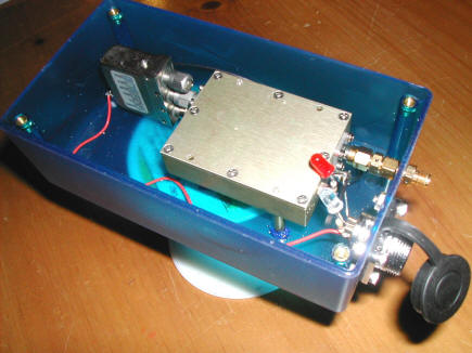
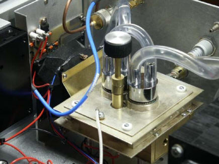
My feedhorn is a VE4MA and optimized for the depth of my dish. In this photo you can see the RX probe side and the low noise amplifier (LNA) is housed in the blue enclosure. Also in the enclosure is an LNA protect relay. When I go to TX mode, a sequencer controls the sequence of events. The first thing that occurs is that the relay disconnects the LNA from the RX probe and terminates it into a 50 Ohm load. Thus, energy from the TX probe that reaches the RX probe cannot destroy the LNA. The RX probe, protect relay and LNA all use mating connectors (male to female, etc.) so that NO adapters or cables are needed. Thus, virtually all of the weak signal received at the RX probe reaches the LNA.

This photo shows the RX probe, DC power connector and SMA output from the LNA (lower right). My LNA was designed by W7CNK and has a 0.23dB noise figure.
There are two methods for tracking the moon:
- Azimuth/elevation. This is similar to a gun turret on a ship. Two motor drives are required and a computer program crunches the numbers and sends commands to the motors.
- Polar Mount. This drive is most often found in astronomical drives and has the advantage of requiring a single motor. Before each operating session, the polar mount declination is set. After that the hour axis motor tracks the moon at a constant 14.5 degrees/hour. This paper, which I presented at SEVHF, gives the details of polar mounts and how my system works.
Here is a photo inside the LNA enclosure. The protect SMA relay is on the left and the LNA in the center. An LED is used to confirm +12VDC to the LNA and another LED confirms that the LNA is in protect mode. These are easily visible through the translucent housing.
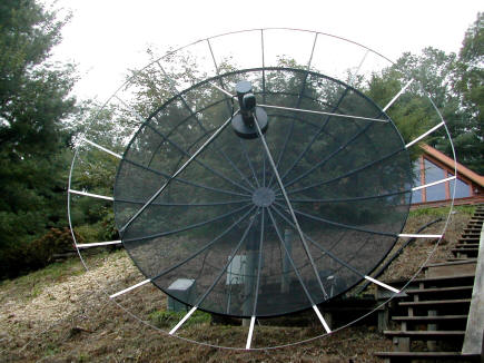
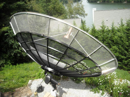
My current dish began life as a 12’ C/Ku TVRO dish. Several years ago I expanded the dish to just over 15’. A template was made up of the curve of the surface from 12' to 15’ and aluminum T channel was bent to fit the curve. Because the focal length to depth (F/D) becomes deeper as one expands a dish, not every surface is a good candidate for expansion. This is because, as the dish gets deeper, it becomes increasingly difficult to efficiently illuminate the surface. My dish was 0.41 F/D which is shallow. After expansion, it is now 0.33 F/D. This F/D is well-illuminated with a VE4MA feed with the scalar ring moved back from the mouth. The exact position of the scalar ring is determined by repeated measurements of sun noise versus cold sky noise. Time spent optimizing the scalar position along with the exact focal point pays off in big dividends when it comes to pulling small stations out of the noise.
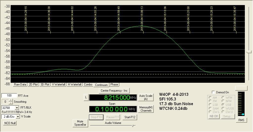
Here is a screen capture using an RF Space SDR receiver set up for measuring sun noise. To do this I position the dish 5 minutes or so ahead of the sun. The sun then passes through the dish’s beamwidth. And then passes ahead of the dish.
The text shows that my sun noise was 17.3dB at a solar flux of 105.3. The sun noise measurement is made as close to possible when the new SFI is published. Measurements made without knowing the solar flux at the time of measurement are useless. Here is the site I use for 10cM solar flux.
Joe, K5SO, has a page giving more information on sun noise and a useful graph that plots sun noise vs solar flux vs dish size. Click the image below for a larger version.
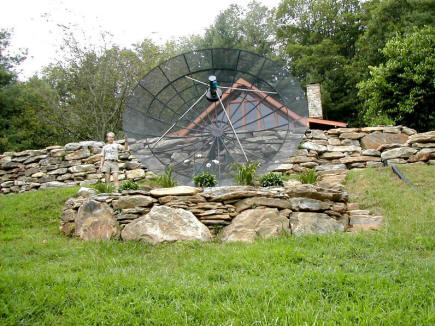
Some pictures of my dish under expansion:
Expansion ribs and trim ring in place.
Expansion mesh in place
Finished dish ready for testing
I have built a number of amplifiers through the years. The first two were 2C39 water cooled.
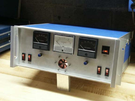
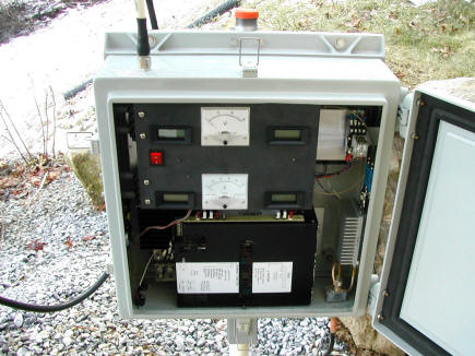
2 X 2C39. The object on the bottom center is a paddle wheel that gives confirmation that the water is indeed flowing. The black meters monitor cathode currents and the center meter is plate voltage. 250W typical output.
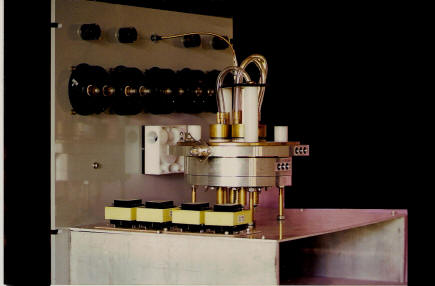
2x2c39 Internal view showing water jackets and plumbing.
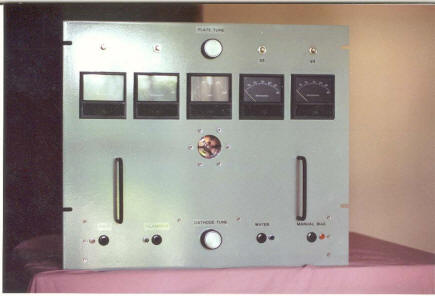
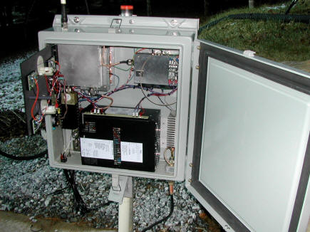
4 X 2C39 water cooled. The 2 knobs tune the input and output while the meters monitor the 4 cathode currents and plate voltage. Once again, a flow meter on the bottom center.
4 X 2C39 again, showing plumbing and the 4 cathode bias supplies.
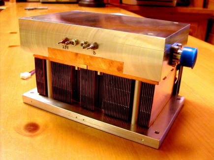
Solid state amplifier employing 17 Mitsubishi modules. One M57762 module is used as a driver for the 16 modules. Typical power out 350W.
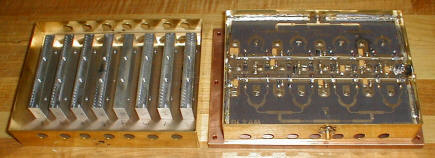
The 16 modules are arranged in two 8 module amplifiers. A 4 port hybrid then combines the two amplifiers. See my latest amplifier for details on the hybrid.
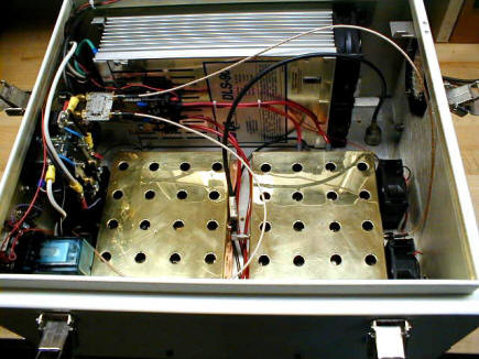
Finished amplifier. The 12VDC @90Amp power supply is at the top. The small silver rectangle is an Anaren 4 port hybrid used to split input power evenly between the two power modules.
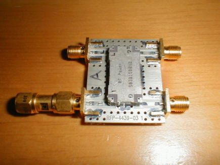
Anaren splitter hybrid.
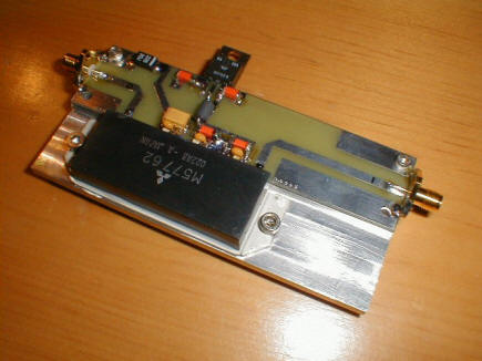
Driver module on custom milled heatsink.
This is my current amplifier using two LDMOS modules yielding 700 watts output.
One of the two amplifiers= 350W each.
Finished amplifier mounted at the dish- overcomes feedline loss.. The black box at the bottom is a 28VDC @50 A power supply. The silver heatsink in the lower right is the driver amp. 0.4W from the shack drives this amp to 16W. The 16W is split 2X to deliver 4W to each of the LDMOS amplifiers. A 4-port hybrid splitter then efficiently combines the two amplifiers, producing over 700W out.
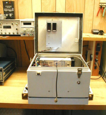
This photo shows the metering door open. One amplifier is in the upper right while the 2nd amplifier is hidden underneath the 4 port hybrid.
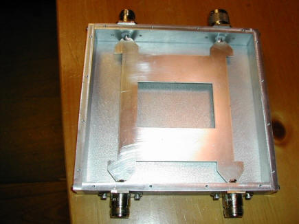
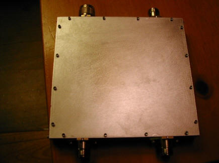
Two photos above are the 4 port hybrid with the silver plated element. Insertion loss is under 0.15dB.
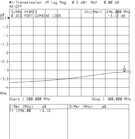
Network analyzer plot of one of the 2 combining ports. Marker loss showing the -0.12dB loss.
The advantage, of course, of having the amplifier right at the dish is that it overcomes any feedline loss from the shack. Even large diameter hardline can easily have 1-2dB loss.