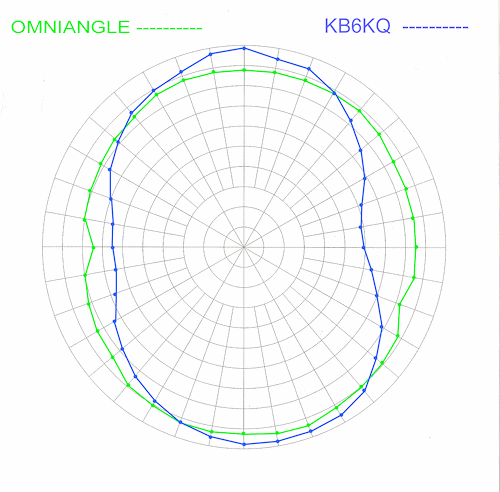
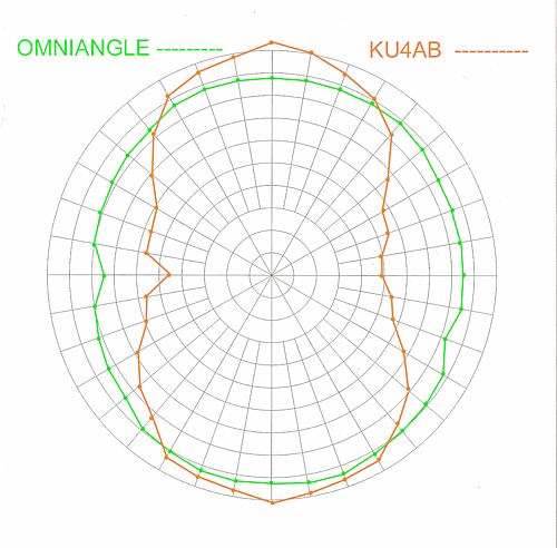
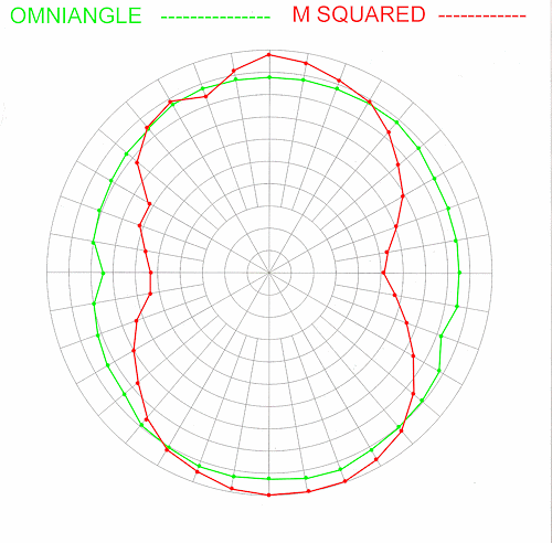
As you view these comparative graphs, there are several things to keep in mind.
- Make sure your video setting is set so that the polar plot circles appear as circles - not as elipses.
- Each ring represents 1dB
- A perfect omni antenna would be a perfect circle, so that is the goal.
- Note the areas where the Omniangle is greater than the competition and those areas where the competition
is greater than the Omniangle. The Omniangle, in every case occupies more area; this translates directly to
more gain.
- At the VHF Conferences, antennas are measured without rotating them; the claim of omni is taken as true
or fact. I have been at these conferences, and the antennas are oriented so that the coax is away from the
receiving antenna and the gap in the antennas is towards the front. You can see why then, an antenna that
has an elliptical pattern would, at first blush, appear to have more gain than the Omniangle. It indeed does -
in that direction. The proper method would be to rotate the antennas every 10 degrees or so
(as was done in our anechoic chamber testing) and measure the gain.
Add up all of the gains figures and divide by the number of readings taken. Compare this number with another antenna
measured in the same fashion. This consumes way too much time for what the VHF conferences allot. But readings taken as they
are leads one to draw the wrong conclusion and would get an engineer fired for incompetence.
These patterns were taken from actual antennas in an anechoic chamber.


CLOSE THIS WINDOW


