 All materials on this site © PAR Electronics, Inc.
PAR Electronics, Inc.
P.O Box 645
Glenville, NC 28736
Voice: 828-743-1338
Fax: 866-304-8479
Email us if you have questions or comments about this site.
Site by
Pinnacle Web Design
Tech Notes
Please select your topic:
End-Fedz
Tuning a Dipole (whether center-fed or end-fed)
Deployment
Preparing the Matchbox End of the Radiator on the EF-10/20/40 for the #10 Lug
Using an EF-20 matchbox on 40M
Using an EF-20 matchbox on 40M - Another Solution
End-Fedz
There is occasionally some confusion concerning the stub we include on all models except the EF-30. Under normal circumstances, you will not need the stub. It only is needed if you cut the radiator too short. One client called it the “oops” stub- and that is appropriate.
Because the ends of a half wave dipole are high impedance they are susceptible to, or see metal objects. Contrast this to the center of a dipole which is low impedance. Metal attached at the center will have close to zero loading effect; this is easily seen in some Yagi designs where the elements are grounded directly to the boom.
So, back to the stub. Should you inadvertently cut the radiator too short, attaching the stub to the matchbox capacitively loads the wire making it look longer electrically.
Tuning a Dipole (whether center-fed or end-fed)
We occasionally get questions as to how to tune the EndFedz series or requests for us to pre-tune the antennas.
One has to realize that an antenna is a function of its environment. That is, the resonant frequency will be a function of:
- How high it is deployed
- How it is deployed (i.e. horizontally, vertically, sloper, inverted L)
- Proximity of close in metal objects and the size of these objects.
- Even soil conductivity
Of course, how high it is deployed is in terms of wavelength. An antenna at 15’ would be high at 2M where a wavelength is only 7’, but at 40M (wavelength of 140’) it is virtually on the ground.
An antenna analyzer is always going to be a great help. For one reason it allows you to find where the antenna is initially resonant- even if it is out of the band. Because we cannot predetermine any of the above, we intentionally supply a radiator that is guaranteed to be resonant at least at the very low end of the band it is designed for. To raise the resonant frequency one always has to shorten the radiator. Sometimes our manuals will give an approximation of how many KHZ resonance will move up as each 1" is cut. This is only an estimate; always proceed slowly.
If you do not have an antenna analyzer, take initial readings at the low, middle and high end of the band. For example for an EF-20, take VSWR readings at 14.0, 14.15, and 14.3 MHz. Out of the box, the antenna will normally be resonant below 14MHz, so typical readings might be:
- 14.0 1.8:1
- 14.15 2.6:1
- 14.30 4.0:1
An antenna analyzer would likely tell us that the lowest VSWR is around 13.85 MHz or so. This indicates the antenna needs to be shortened. If you operate mostly CW, you might want to tune the antenna to 14.030 MHz or so. For phone, 14.20 MHz would be appropriate. If you operate phone and CW evenly then shoot for the middle of the band.
We encourage you to tune the antenna deployed at the location (height etc) that you will be ultimately using it.
Deployment
A common question is: “What is the best way to hang the antenna?”
The answer will ultimately depend on what your use is, as each orientation has both advantages and drawbacks.
- Horizontally deployed antennas (each end about the same height above ground) tend to be quieter than vertical antennas. For low heights (under ½ wavelength), horizontal antennas will have the highest gain at very high takeoff angles- this is great for close in work, but not optimum for DX. Does this mean you will not work DX with, say, a 40M antenna at 30’ high? No, but you will not be as loud to a DX station if you were able to hang the antenna above a half wavelength (66’ @ 40M).
- Verticals are omnidirectional, have a low takeoff angle (good for DX) but also tend to pick up more man-made noise.
- A sloper, as you might guess, is in between a horizontal and a vertical. It can have another advantage though in that it will be somewhat directional- towards the direction of the bottom of the antenna. If the high end is East and the low end West, the sloper will have perhaps 3dBd of gain to the west and a front to back ratio of 7-8dB. This can be an advantage if you essentially wish to work one direction, and attenuate signals from the opposite direction.
Preparing the Matchbox End of the Radiator on the EF-10/20/40 for the #10 Lug
Whenever one terminates a wire in a lug etc, a weak point is created at the transition and continued flexing could cause the joint to fail. In addition, because we use a lug that is really made for a larger diameter wire (we use this lug because of its thicker material), there is also the possibility, that with long term strain, the wire could possibly pull out of the lug's barrel. In order to avoid either of these failures, PAR has come up with the following method to attach the lug. We have never had a failure reported.
Using an EF-20 matchbox on 40M
This concept might appeal to portable users. The EF series matchboxes (with the exception of the EF-10/20/40) are essentially a low pass filter.
As such, the EF-20 matchbox for example appears as a series inductance at frequencies well below 20M. At 40M this series inductance is enough to shorten a 33’ vertical monopole to approximately 24’ physically.
As such, the EF-20 matchbox for example appears as a series inductance at frequencies well below 20M. At 40M this series inductance is enough to shorten a 33’ vertical monopole to approximately 24’ physically.
Because the electrical length is 33’, the radiator will b e a low impedance, or current fed antenna. As such it will require a counterpoise.
Recall that an ideal quarter wave monopole over an infinite conducting surface has a radiation resistance of around 37 Ohms (1/2 of a free space half wave dipole). As one electrically shortens the radiator from a full quarter wavelength, Rrad drops further.
Experiments show this value to be around 24 Ohms ( 2:1 VSWR) when the radiator is around 24’, strung vertically, or as a sloper The counterpoise is around 33’ and deployed horizontally above the ground. The feedpoint resistance can be raised by placing a capacitor from the SO-239 center conductor to shell (ground)
So with these concepts in mind, one can effectively use an EF-20 matchbox on 40M by:
- Disconnecting the factory 33’ radiator and reinstalling it as a quarter wave counterpoise. One way to do this would be to use a hose clamp to compress the #10 lug between the clamp and the PL-259 shell.
- Attaching a 24’ vertical radiator to the matchbox #10 lug.
- Attaching a 560pF capacitor between the SO-239 center to shell (ground).
The figure below is a plot after the above mods have been performed:
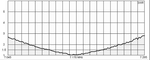
We hope to supply a kit consisting of the 24’ radiator/end insulator and an adapter that would screw onto the EF-20 matchbox and consist of a shunt 560pF capacitor and an SO-239 connector.
Of course, the same concept may be applied to an EF-40 to be used as a quarter wave on 80M or an EF-10 to be used on 20M. The cap value will have to be changed accordingly.
For those that operate portable, this would be an easy way to add another band capability by simply carrying an extra wire and the adapter.
Using an EF-20 matchbox on 40M - Another Solution
The advantage to the first modification is that it allowed for a shorter radiator- approximately 26’ and the 560pH shunt capacitor yielded a near perfect center frequency match. This solution uses the original 20M radiator and also employs a 33’ radial. In addition a female/female/male UHF Tee connector and a shorting strap are used. See the figure below.
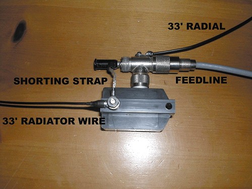
We modified the T connector to accept a ground lug by drilling a #43 hole and tapping it for 4-40. Caution MUST be used so as not to short out to the center conductor pin. An easier solution would be to use a small hose clamp to attach the 33’ radial to the T connector. The shorting strap effectively shorts out the inductor in the matchbox leaving only a small shunt capacitor between radiator and ground. Its effect is negligible.