 All materials on this site © PAR Electronics, Inc.
PAR Electronics, Inc.
P.O Box 645
Glenville, NC 28736
Voice: 828-743-1338
Fax: 866-304-8479
Email us if you have questions or comments about this site.
Site by
Pinnacle Web Design
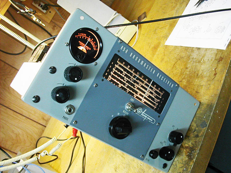
Vintage Radio Restoration - Harvey Wells R-9A Receiver
The Harvey Wells company began in 1939. The principals were Cliff Harvey W1RF and John Wells W1ZD.
The 1st amateur receiver I am aware of was the R-9. Ham band only (80-10M) with 10 tubes including the OA2 VR tube and a 5Y3 rectifier. Dual conversion with 1600KHz and 260KHz IF. Mixers for both stages were 6U8As. This version was produced from 1954 to 1957 and sold for $150. Its small size lent itself to both mobile and fixed station use. A companion T-90 (and a variant TS-90 which included 6M) made for an elegant set of twins.
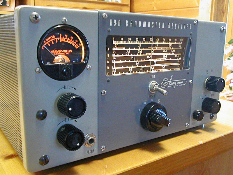
The R-9 was replaced by the R-9A in 1958. According to Osterman, this receiver was closed out in December 1958 for $90. A few of a general coverage version were made for RCA. I have only seen one of these in captivity.
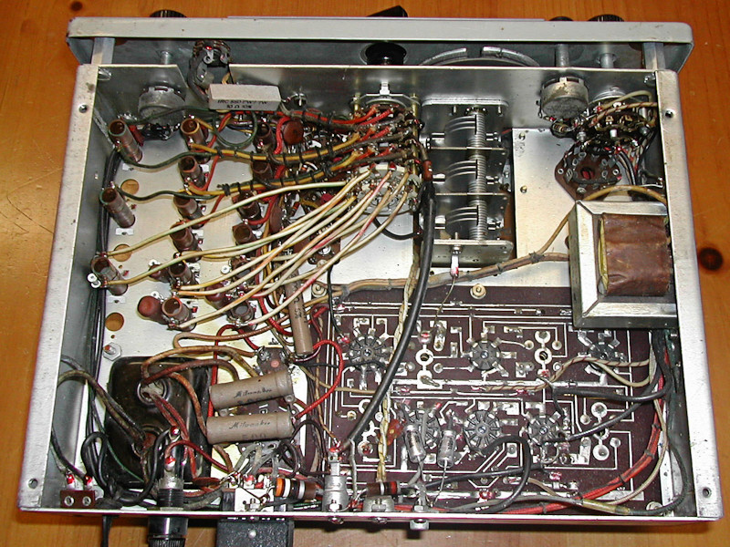
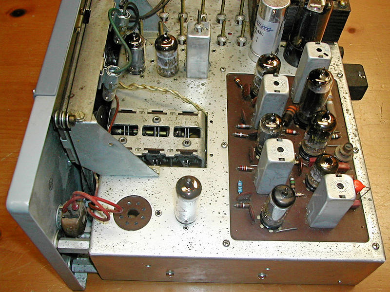
The primary difference between the 9 and 9A is that the 9A used a printed circuit board for 6 of the tubes and their components.
I bought mine from eBay. When it arrived, the tuning knob did not move the dial pointer. After removing the front panel it was observed that the phosphor bronze pinch wheel had a crack in it. Cleaning and silver soldering resolved that issue. I then bought a new 2 section electrolytic can and (2) replacement cathode bypass electrolytics. These were installed and then… the receiver sat for a good 6 years.
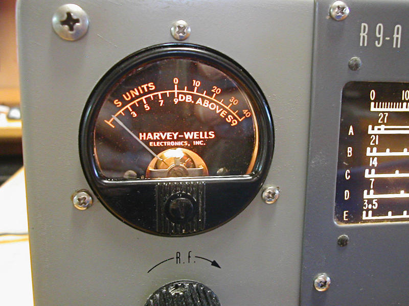
In November 2019, I had renewed interest in the project. The loose S meter dial glass was cleaned and reattached.
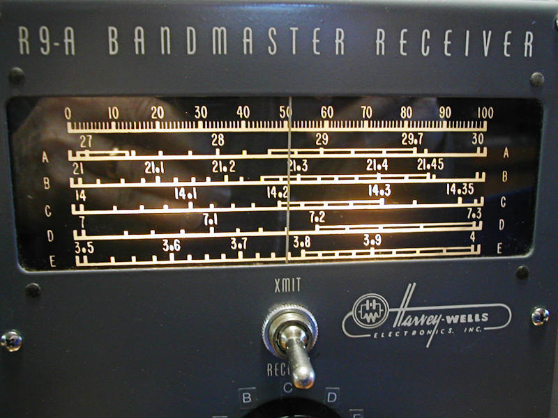
On most R-9 receivers, the 5 bandswitch designators (A-F) are missing due to the fact that the silk screened letters are right on the perimeter of the combination bandswitch/tuning knob. They simply wear off.
The front panel was thoroughly cleaned and a coat of Rejex polymer applied to protect it. All knobs were cleaned and reinstalled. The bandswitch knob is a press-on knob and its spring steel insert was missing so a new one was made. The tubes were removed, cleaned and DeOxit was applied to the pins with Q tips.
Onto the electrical. After applying power, the only band functioning was 80M and signals were weak and well off-frequency. Following the manual procedure, the 1st and 2nd IFs were aligned as was the BFO. Signals were a bit stronger and I now heard my signal generator on 10M in addition to 80M. Tapping the chassis would result in stronger signals temporarily. This problem was eventually located to be the center grounding post of the 1st mixer/oscillator 6U8A tube. Instead of being 0 Ohms to ground, it had 14 Ohms and that value changed as the center stud was moved. So, that pin was externally grounded to a close-by terminals trip. System gain shot up by 14dB. Now things were stable, the S meter moved a bit but it was obvious by doing a Minimum Discernable Signal test (MDS) that things were still not right. I had previously done some tube pin voltage tests and replaced a 100K resistor which brought the plate of one of the tubes into spec. I now reviewed my results and found the control grid of the 1st mixer/oscillator tube was 0.3V where it should have been 30V. That voltage was derived through a 1M resistor. Measuring that resistor showed it to be open circuit. A bear to get to but the new 1M resistor was installed and system gain shot up by 31dB! Now the receiver was really hot. MDS was better than -130dBm. Voila.
There is no facility for tracking the VFO, but amazingly it is excellent as-is.
40M still showed no signal from my signal generator so I attached my Rohde & Schwarz FS-300 spectrum analyzer. The VFO runs 1.62MHz above the desired frequency. In this case it was 5MHz high.
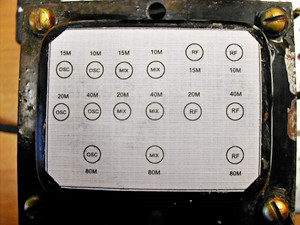
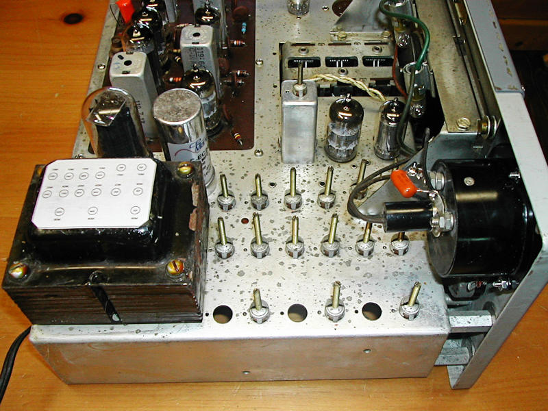
Backing up a bit, there are (3) inductor adjustments for each band — Oscillator, Mixer, and RF stage. The manual is clear that alignment MUST begin on 10M and work lower to each band. This is because the inductor for 10M is paralleled for 15M. On 20M, 10M and 15M inductors are paralleled and so on. I have seen this technique on other rigs. I believe the previous owner did not follow this procedure and as a result it is impossible to align the receiver. One could align 80M and then 40M. Going back to 80M the alignment is way off.
 But
here is where it got complicated. The inductor locations for
each band — as spelled out in the manual — were wrong. One out
of 15 was correct! Many hours later I had figured out the
correct locations for each band's 3 coils. To keep a future
owner from going insane, I made a template of their locations
and used rubber cement to glue this to the top of the power
transformer.
But
here is where it got complicated. The inductor locations for
each band — as spelled out in the manual — were wrong. One out
of 15 was correct! Many hours later I had figured out the
correct locations for each band's 3 coils. To keep a future
owner from going insane, I made a template of their locations
and used rubber cement to glue this to the top of the power
transformer.
Now, the receiver is really fun to use. AM is spectacular and CW/SSB is typical of early receivers with a BFO. There is a knob for fine tuning the BFO and this makes it a snap to tune in these signals.
While it can be frustrating at times, and I lose sleep over thinking of how to solve the issues, in the end there is a wonderful feeling of accomplishment, new respect for the original designers, and a clearer understanding of the receiver's circuitry. If these vintage rigs worked out of the box, none of that would be attained.
Please click each image below to enjoy a larger view.
 |
 |
 |
 |
 |
 |
 |
 |
 |
 |