 All materials on this site © PAR Electronics, Inc.
PAR Electronics, Inc.
P.O Box 645
Glenville, NC 28736
Voice: 828-743-1338
Fax: 866-304-8479
Email us if you have questions or comments about this site.
Site by
Pinnacle Web Design
Vintage Radio Restoration - Transcom SBT3
I first learned of the existence of the Transcom on the front cover of the September 2015 issue of Electric Radio magazine. Now I thought I knew of all the early SSB transceivers, and yet here was this diminutive rig that I had never seen and certainly had no knowledge of.
An email to one of the hams on the cover, Mark/NU6X brought some replies and a possible source of an SBT-3. I was able to buy that SBT-3 along with the mobile power supply and eventually also found a parts chassi
The SBT-3 is a very interesting and cleverly designed transceiver for its time: the mid 1960s.
The owner/designer of the SBT-3 was Cal Heisinger, W9TRG of Wisconsin. Prior to Transcom, Cal worked for Lakeshore Industries of Manitowoc, Wisconsin. Lakeshore is well remembered for their early phasing type SSB transmitters and the Bandhopper VFO. He later joined Gonset Corp. as an electrical engineer. When Gonset bought a building in Los Angeles in the late 1950s, Cal moved west with them and obtained his W6MNH call. Later, Gonset bought a building in Encinitas and Cal moved to Escondido to be closer to the Gonset plant. After leaving Gonset, Cal worked for Minitron, a manufacturer of Citizens Band gear. I have been unable to locate any MiniTron radios.
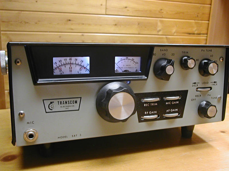
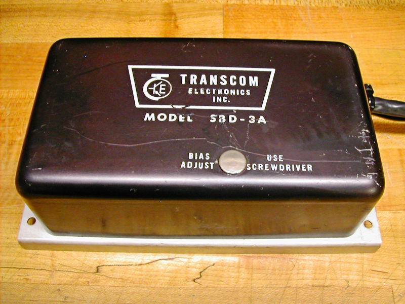
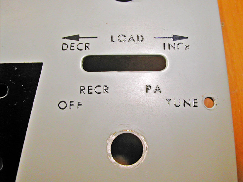
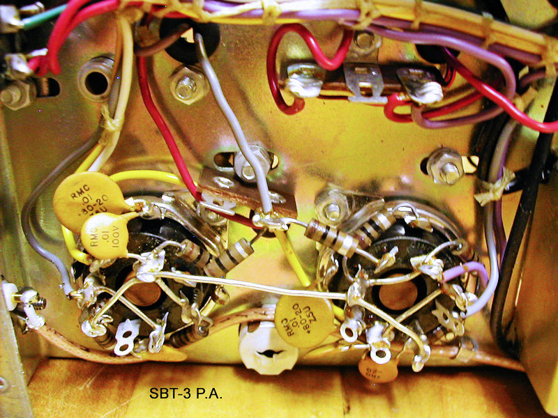
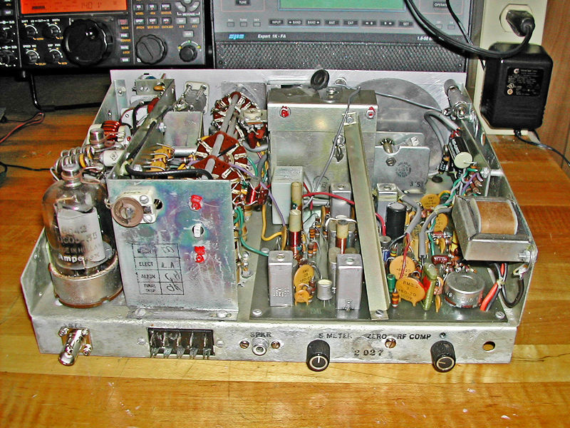
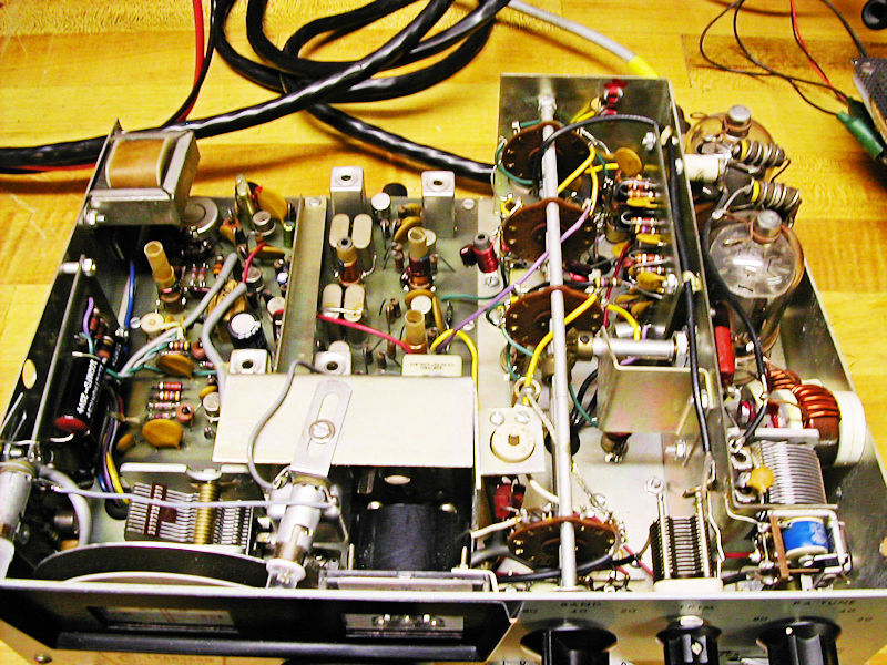
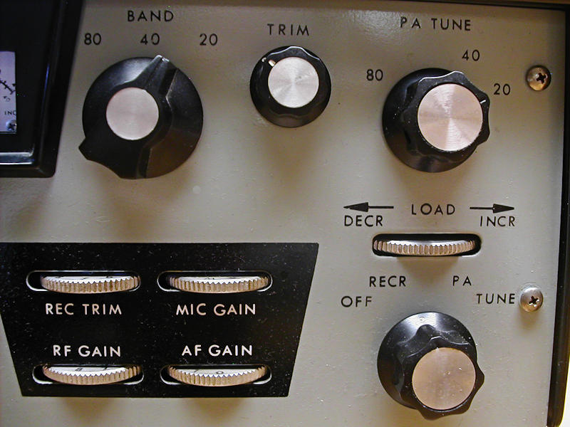
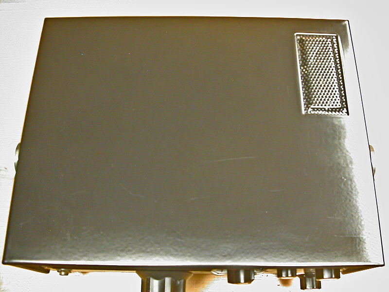
Amateur radio remained his first love however, and he left Minitron to start Transcom and manufacture a small amateur transceiver- the SBT-3. The SBT-3 is a small (11.5 X 9 X 4.5”) SSB only transceiver for 80, 40 and 20M bands. The rig employed some very novel circuitry including a varicap tuned front end (RCVR PEAK), a very clever VFO and mixing scheme, a solid state PA driver (3X SM4710 Ge PNP) and a pair of instant heat 6146 finals (type 8042).
At its peak, Transcom had 2 production lines running employing 10 women. While amateurs appeared to really like the SBT-3, Cal had difficulty collecting payments from his amateur dealers. As a result, he began selling directly to amateurs and also designed a commercial version of the SBT-3. One order of 200 units went to the Philippine government.
No one seems to know how many SBT-3s were produced but the number must be small as the rig remains rare and is a collectors' item today.
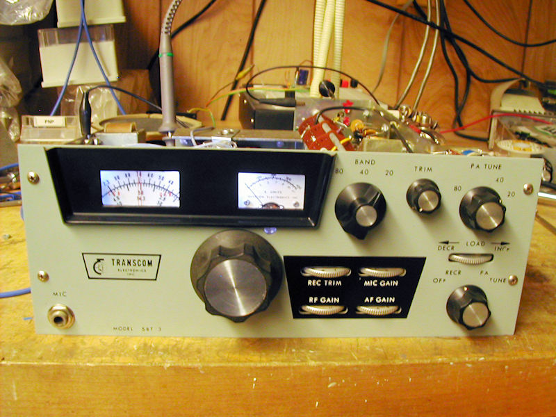
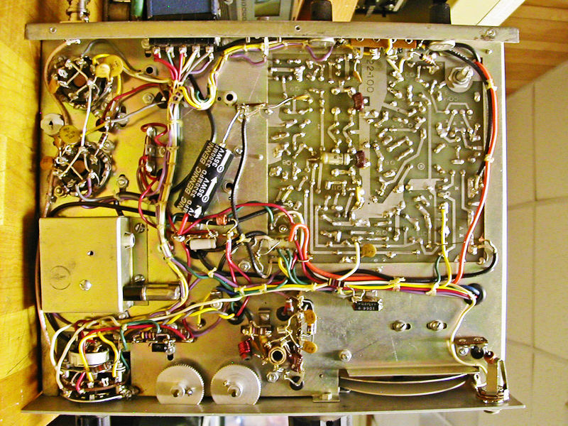
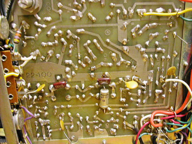
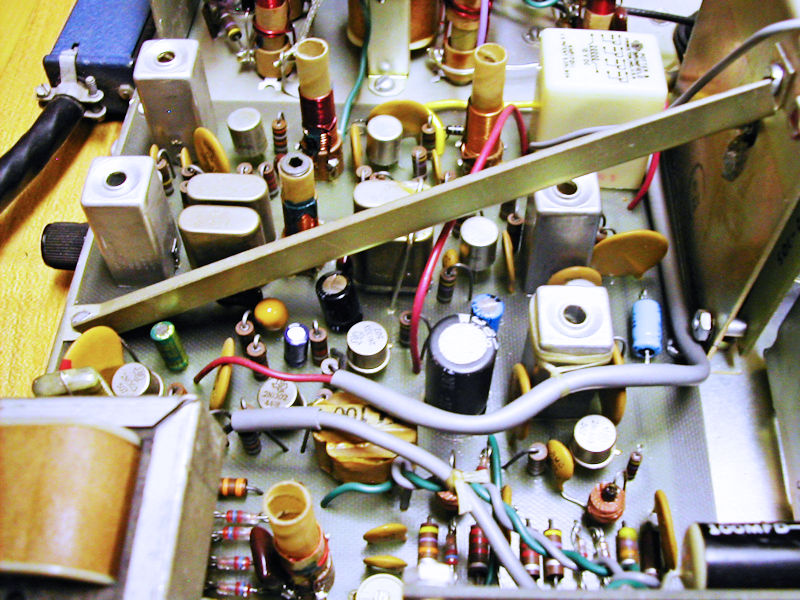
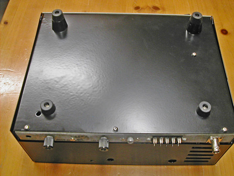
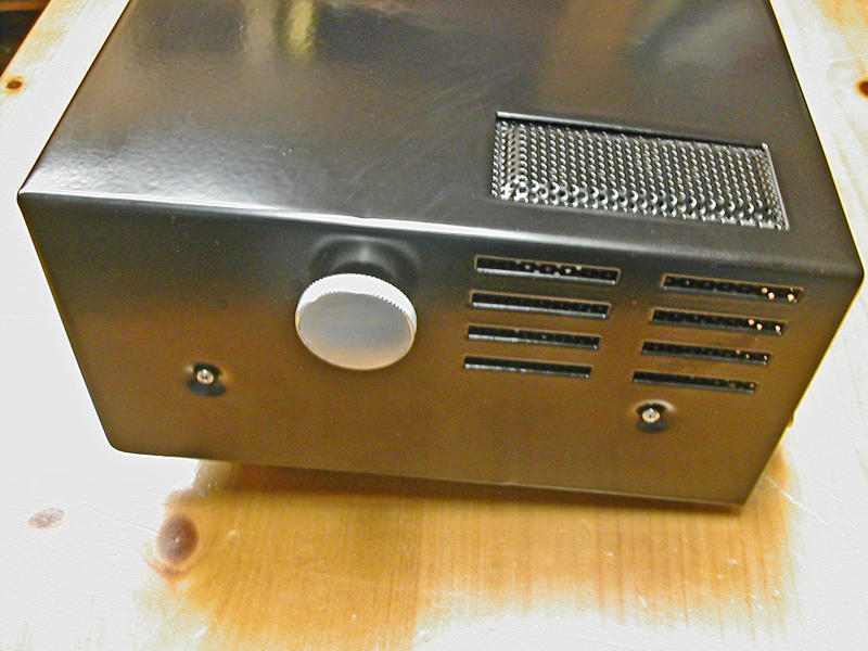
When I received the SBT-3, neither the receiver nor transmitter worked. I traced the receiver issue to the receive mixer transistor: a 2N2092. This is a PNP Germanium transistor with 4 leads: one being the case which Transcom grounded. Years later, this device shows a propensity to develop an emitter to case short. Sometimes, the transistor can be 'restored' by simply clipping the case lead from ground. I found an NTE126 to be a good replacement. That got the receiver working. Alignment had held all these years later. Word on the street was that the transmitter mixer was also prone to failure. Unfortunately, working on that board (which also contains the three driver transistors) is a bit of a nightmare. At this stage, I had the cabinets and PA screen powder coated and used the rig for monitoring. Now, some 5 years later, I became interested in the rig again.
My thought was to first prove that the transmitter issue was indeed a bad TX mixer transistor. The first thing I did was check for 12V going to the TX mixer/driver board- nothing. The next suspect was the R/T relay that switched +12V to the mixer board. The relay proved to be fine and its contacts were cleaned with DeOxit. Following backwards, I found a distribution point for +12 on a terminal strip. A little inspection showed that the +12V wire to the T/R relay had never been soldered. Likely when the wire and strip were new, the mechanical connection was enough to supply the +12V to the mixer/driver board. Oxidation over 50 years, however, resulted in a high resistance. I soldered the connection and for the first time saw P.A. plate current! Again, trying to peak up the transmitter with an alignment resulted in no improvement. The only adjustment was to the TX balanced modulator to null the carrier. I see about 55W out on 80 and 20M and about 35W on 40M. W9RAN has correctly pointed out that the lower 40M power is likely caused by the heterodyne oscillator having to be multiplied for 40M operation.
The TX audio chain appears to be only an emitter follower that transforms the mic impedance but provides no voltage gain. I and others believe the rig really could benefit from an amplified microphone. Audio reports are good and the discrete 4 crystal filter seems to provide adequate opposite sideband and further carrier suppression.
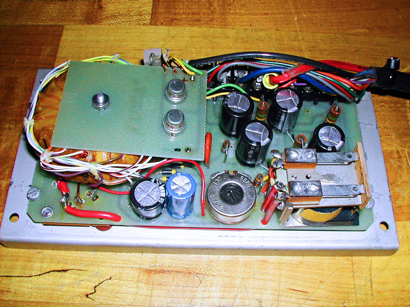
Cal was not much on documentation. Four pages of text, a block diagram with some errors and schematics of the AC and DC power supplies and the transceiver.
Apparently, poor cash flow from dealers continued to haunt the business and the company sold to L. Robins of La Mesa, CA in March of 1969.
Regards,
Dale
 |
 |
 |
 |
 |
 |
 |
 |
 |
 |
 |
 |
 |
 |
 |
 |
 |
 |